|
INSTALLATION
INSTRUCTIONS
Russ Wernimont
Designs, Murrieta, CA
(951) 698 9495
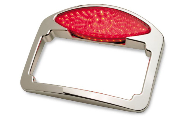
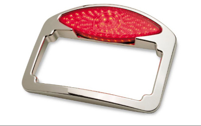
RWD # 3217 LED Cat Eye Taillight (Part Number 2010-0010)
The RWD Combination Cat Eye Taillight License Plate system uses
bright Red “Run/Brake” LED lights with “Embedded
Arrowhead” Amber flashing turn signals and LED License plate
lights all mounted in a Chrome License mount frame that includes
plug-in wiring for H-D factory stock 96-up Softails, 97-up Rubber
mounts, and 99-up Sportsters. This system can also be spliced-wired
to most motorcycles using run/brake taillights and separate turn
signals.
Contents:
Qty - Description
1 Chrome Taillight assembly with extension wire & Instructions
1 Empty 5-Pin connector housing
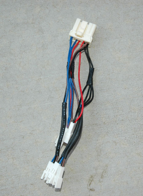
1 6-Connector H-D wire interface assembly
2 Turn Signal extension wires
1 Plug-In Load Equalizer
4 Pr’s ¼-20 x 3/8” Hex bolts & Compression
Washers
1 Dielectric grease Pak
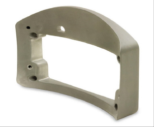
RWD Custom mounting adapters available:
RWD Part Number # Description
2010-0011 RWD-260 Weld-in flush mounting “Bucket” for
complete Taillight License mount
2010-0012 RWD-3181 Chrome Replacement Mount for all Stock Harley
Davison “FL” series
2010-0013 RWD-3177 Chrome Surface mount for most custom and “OEM”
fenders
2010-0014 RWD-3167 Weld-On Swing Arm Mount
2010-0047 RWD-FB9 “BOB-Tail” Fender Mount
Installation
CAUTION: A qualified service technician should assist with this
installation if you are unfamiliar with
motorcycle wiring.
“Plug-In” 96 -up H-D models (See Section “F”
for splice-in applications)
A. Installation to Fender
1. Disconnect both battery terminals.
2. Remove any non-OEM wiring adapters, load equalizers, etc.
from present taillight wiring under seat
so the remaining wiring is H-D “stock”.
3. Remove seat.
4. Remove OEM Taillight and rear fender wiring and prepare to
install Mounting Adapter of choice.
5. Trim license plate and re-size holes as needed to test fit
taillight hole pattern.
6. Carefully press taillight wire into wire exit channel in back
of taillight housing and thread the wires
out through the wire exit hole of taillight mounting adapter.
7. With license plate in place, secure Taillight into mounting
adapter with 2, ¼-20 bolts and washers.
Torque bolts to 10 Ft/Lb max.
8. Carefully wrap together open connector pins with masking tape
and thread taped end of taillight wire
through fender wire clips or tubes (depending on type fender
used) and route out of fender under seat
area near main H-D harness connector for rear fender.
9. Bolt Taillight/Adapter set in place on fender and make sure
rear wheel will always clear taillight
wire.
B. Connecting Wires (If your bike does not have the large 8-pin
matching connector, go to section “G”)
1.Insert empty 5-pin connector housing into mating 5-pin connector
of H-D wire interface assembly
2.Remove masking tape on 5 taillight wire pins and loosely insert
pins into empty housing so they match
same color and sequence of interface connector wires.
a.Pin 1, Blue, Main Taillight Run Power (Powers ALL functions
of Taillight operation).
b.Pin 2, Red, Brake signal.
c.Pin 3, (MIDDLE PIN) BLACK GROUND WIRE.
d.Pin 4, Violet, Left Turn Signal
e.Pin 5, Brown, Right Turn Signal
3.Starting with blue pin, carefully reinsert each pin so locking
tab of pin is oriented to “snap” into pin
lock of empty connector in the order of 2. a – e. color
code.
4. Plug large white 8-Pin interface assembly connector into mating
OEM connector from main harness
5. Plug small 5-pin connector from taillight into matching interface
assembly connector.
C. Load Equalizer and Turn Signals;
1.Load Equalizer;
a.If taillight is used with no additional rear turn signals,
connect 3-pin connector from load
equalizer into matching interface assembly connector to “balance”
turn signal flasher load.
b.If OEM or other external turn signals are used, test turn signal
flashing function without load
equalizer and only connect load equalizer if required to make
turn signals flash correctly.
2.Turn Signals; Two turn signal extensions are provided to connect
turn signals as desired.
a.If OEM or other side-mounted turn signals are used, splice
the Violet extension wire to the
positive turn signal lead and splice the Black extension wire
to the negative turn signal lead.
b.Connect the small 2-pin turn signal extensions to matching
interface assembly connectors.
NOTE, Reverse connections as needed to make right and left flash
correctly.
Use Dielectric grease on all connector ends at final installation
of all details.
D. Extra Power connector; An extra 2-pin accessory circuit power
connector is included in the interface
connector assembly for fender tip lights or other lighting accessories
requiring “run” power.
E. Reconnect Battery and replace Seat
F. Test; All taillight and optionally wired turn signals should
operate with run, brake, and turn controls. If
the battery is low the taillight functions could malfunction
until the engine is running.
G. Connecting Wires when your bike does not have the large 8-pin
matching connector
1.Remove masking tape on 5 taillight wire pins.
2.Cut the pins off, and splice each wire according to the following
color codes to the correct main
harness wires for the taillight.
a.Blue, Main Taillight “Run” Power (Powers ALL functions
of Taillight operation).
b.Red, Brake signal.
c.BLACK GROUND WIRE.
d.Violet, Left Turn Signal
e.Brown, Right Turn Signal
|